Devices
A device is a connection with a profile. The profile binds a source to one kind of equipment: it sets the catalog the camera reads, the state labels, the roll-up and the alarm conditions. The profile's family sets the panels that can show the device.
| Family | Profiles | Panels |
|---|---|---|
| Robots | ABB Robot over Robot Web Services | Robot panel, pose figure |
| CNC machines | Mazak CNC over MTConnect | CNC panel, axis panel |
| UPS | UPS-MIB over SNMP for any vendor, APC UPS over SNMP, APC UPS over Modbus TCP | UPS panel |
| ATS / PDUs | Tripp Lite ATS / PDU over SNMP | ATS / PDU panel |
Each family has a page in this section. The profiles page lists every address a profile reads.
Add panel
In the overlay editor, choose Add panel… under Panels.
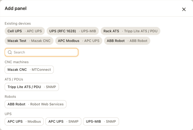
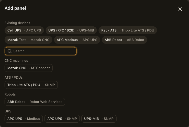
- Device. The dialog lists the existing devices first, then the picker's families. Pick an existing device to bind the panel to it, or pick a profile to add a new device.
- Panel kind. A family with several panels asks which one: a robot panel or a pose figure, a CNC panel or an axis panel. The other families place their panel at once.
- New device. For a new device, the connection form opens with the profile's defaults. Set the source's fields, choose Test connection, then Save & add. The camera adds the connection and places the family's default panel bound to it.
- Save & apply. Until then, a panel bound to a new connection reads SAVE & APPLY TO SHOW DATA.
The Connections page adds a device the same way, without placing a panel. See Connections.
Panels
A panel is bound to one device under its connection setting, Robot connection, CNC connection, UPS connection or ATS / PDU connection, and creates the managed tags it reads. Detail level picks one of three layouts.
| Detail level | Shows |
|---|---|
| Chip | The device name and the roll-up status. |
| Compact | The chip, then the device's main states and values. |
| Full | The compact panel, then more rows and the alarm row. |
The panel's height follows its detail level and base font size, so you set only its width. The alarm row shows the device's active alarm. While the device does not answer, the panel shows a NO LINK chip with the time of the last good read and dims the last-known values. Each family page describes its panels' rows.
Roll-up
Every device has a roll-up, a worst-of summary of its health with the same seven values for every family. The panel's chip shows the device's own state label, such as GUARD STOP, FEED HOLD or ON BATTERY, in the roll-up's color.
| Roll-up | Color | Meaning |
|---|---|---|
| RUNNING | Green | The device runs normally. |
| IDLE | Gray | The device is up and not running. |
| WARNING | Amber | The device runs with something to look at: a recent robot error, a feed hold, a UPS on battery or on bypass, or an ATS on source B. |
| ALARM | Red | An active fault, a guard stop or emergency stop, or a checked alarm condition. |
| STOPPED | Gray | The output is off. |
| NO DATA | Gray | The device answers but reports nothing. |
| OFFLINE | Gray | The device does not answer. |
Each family page maps its states onto the roll-up. The roll-up is a managed state tag, so the state charts and derived states can use it, and the DataBorder carries it pinned.
Alarm conditions
A profile with alarm conditions shows them as checkboxes under Alarms on the connection form.
- A checked condition raises the roll-up to ALARM, shows in the panel's alarm row, and fires the alarm burst in the DataBorder.
- An unchecked condition changes its tag, so history, the DataBorder and state strips see it, and raises nothing else.
A condition clears when the device clears it. The profiles page lists each profile's conditions and which ones a new connection checks. Robots and CNC machines take their alarms from the controller and have no conditions to choose.
Managed tags
A panel creates one managed tag per address it reads, and the driver creates tags for the axes, inputs and outlets it finds. The Tags page describes them.
DataBorder records
The DataBorder carries a device's managed tags as records named d0. followed by the field, for example d0.rollup and d0.state. The digit is the device's position among the devices. The DataBorder page describes the records and the alarm burst.